Final Report for Practical Work of the Course ENGG1300 of Group C9 — 3/5
Table 1. Compaison of the overlapping and side-by-side connection methods.
Aspect Overlapping Side-by-side
Load Distribution Across all layers via friction and interlocking Concentrated at the joint
Strength ∝ number of layers × strength of one layer ∝ adhesive shear strength
Stiffness High due to composite action Low due to tape not structurally integrated
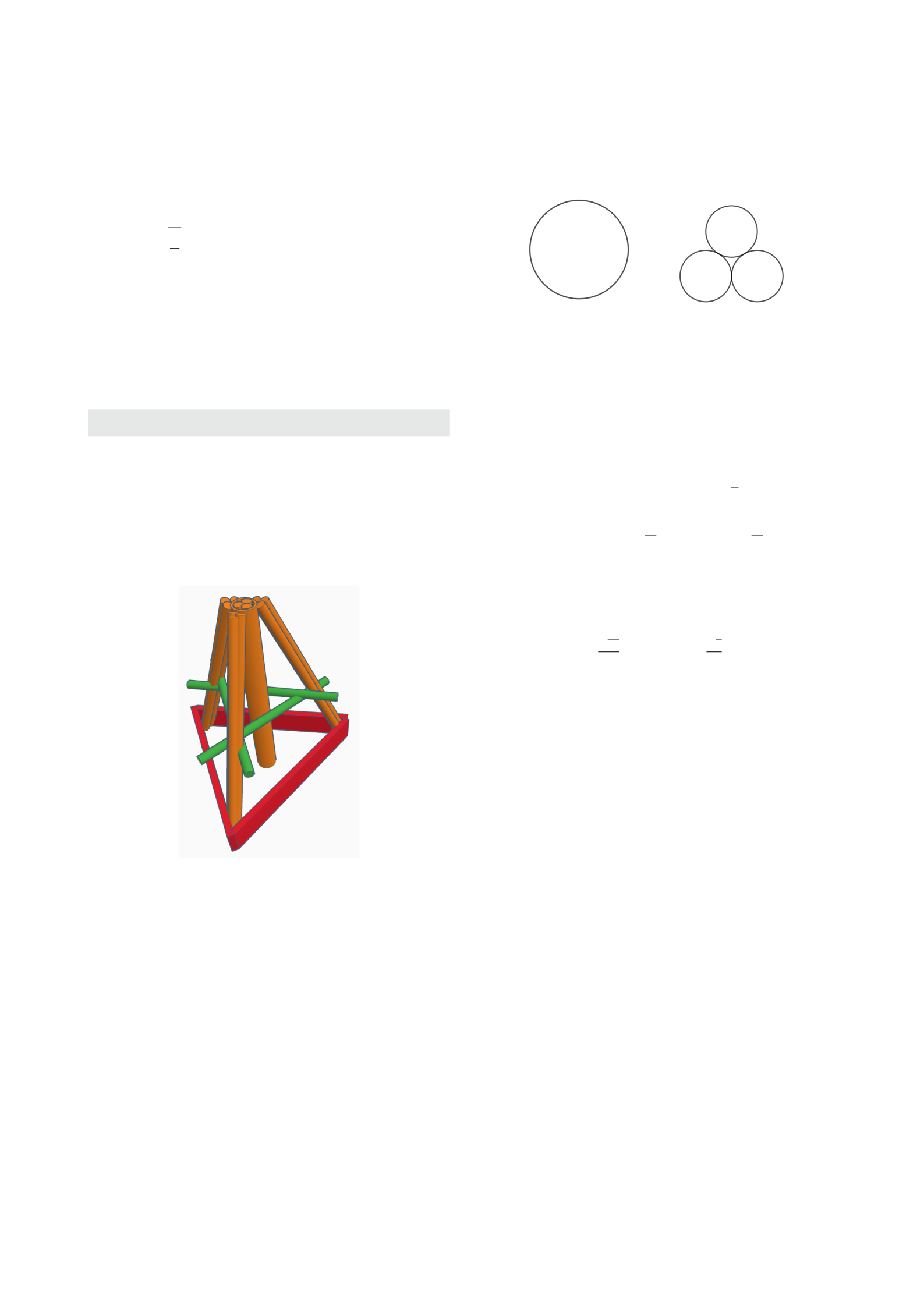
2.3 Restraining Piece
Since the major members are slanted, it was projected that
the vertical compressive load would decompose into down-
ward vertical component and horizontal component directed
away from the centre at the end of the slanted members.
When the horizontal component is larger than the friction
between the major members and the ground, the members
would start to slide away from the centre, which would
lead to most of the load being redistributed to the central
member.
To restrain the horizontal movements of the members,
the group has designed a restraining piece. The piece was
made of several layers of continuous newspapers folded
into a belt-like shape, which was then wrapped around the
base.
Due to its continuous nature, the full potential of the
paper fibres could be utilised to provide tensile strength.
It was expected that when the members start to slide, the
restraining piece would be able to counteract with its tensile
strength.
3. First Trial
The model for the first trial was built with the following
specifications:
1. Weight and Height: Within the limits.
2.
Newspaper Used: Mainly the Sing Tao Daily (
星島
日報).
3. Adhesive Tape Used: Scotch Magic Tape (3M).
4.
Design: The supporting members did not observe the
design as described in section 2.2. However, those
members did not have significant impact on the anal-
ysis of the model.
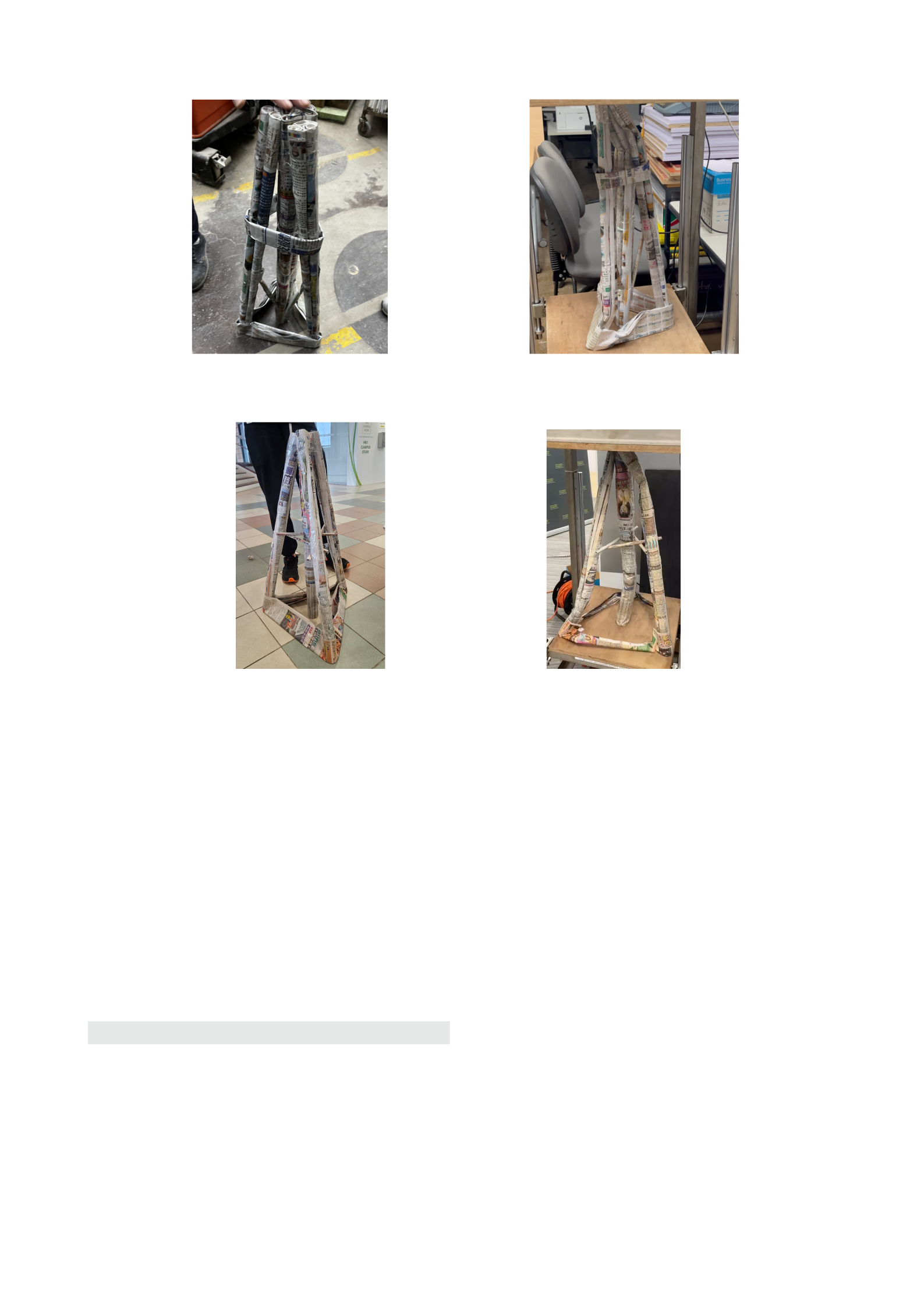
The model is shown in Figure 3a.
3.1 Results
The first model failed to withstand a minimum load of
500 N
. The model was able to withstand a load of
480 N
before deformation occurred. It was observed that buckling
occurred at the major members at a short instant after the
load was applied (as shown in Figure 3b). Of all the mem-
bers, the three external slanted members were the first to
buckle, while the central vertical member experienced the
most deformation.
3.2 Rationale of Failure
After inspection of the failed model, the group has identified
three major reasons that contributed to the failure of the
model.
3.2.1 Low Density of the Major Members
All of the major members in the model were fabricated with-
out aid of any tools. The newspaper pipes were rolled by
hand, leaving large gaps between the layers of newspapers.
This resulted in a low density of the major members.
To quantitatively analyse this issue, the gap-interleaving
members can be approximated as a hollow cylinder of inner
radius
r
and outer radius
R
and compared with a solid cylin-
der of radius
R
. The moments of inertia of the two models
are
I
hollow
=
π
64
(D
4
−d
4
)
and
I
solid
=
π
4
D
4
. It is trivial to see
that
I
hollow
< I
solid
. By Equation 1, the critical load of the
hollow cylinder is less than that of the solid cylinder. This
shows that the hollow cylinder is more prone to buckling.
Furthermore, during fabrication, the newspapers might
have been rolled unevenly, resulting in folds and wrinkles
on the surface of the pipes. This further reduce the stability
of the major members.
3.2.2
Presence of Weak Points at Paper-to-Tape Junc-
tions
While applying the adhesive tape on the pipes, the surfaces
of the pipes were not thoroughly covered, resulting in sur-
faces that were exposed to air. This led to inconsistent
surface stiffness as surfaces with adhesive tapes are stiffer
than those without. When under compressive pressure, the
joints at which surfaces with discontinuous stiffness meet
are prone to buckling.
3.2.3
Imbalance of Load Distribution Due to Mismatched
Lengths of the Slanted Members
The group was not rigorous in measuring the lengths of the
slanted members. Prior to the first trial, the group has no-
ticed that the structure was unable to support itself evenly on
all columns, and that one of the slanted members remained
not in contact with the ground. This resulted in an imbal-
ance of load distribution. During compression, the stress
was concentrated on the central member and the slanted
members that were in contact with the ground, while the re-
maining member acted as a Zero Force Member. As a result,
some of the members were subjected to stress that exceeded
the designed limit and buckled, which is consistent with the
observation.
3.3 Measures Taken for Improvement
In order to address the issues identified in the first trial,
the group has taken the following measures to improve the
model in fabrication of the model for the final trial.
3.3.1
Rolling the Members with Tools to Increase Den-
sity and Avoid Defects
The group has used thin cylindrical wooden rods to assist
in rolling the newspapers into pipes. The rods were placed
on the newspapers while rolling, such that the newspapers