COMP2120-Assignment4
File description: Assignment 4 of COMP2120 (24/25 Spring) with solutions.
Document status: LTS
Last modified: 2026-09-11 21:12 HKT

Attachments
The extra code files needed for this assignment are available. Click the button above to download them in a zip file.
COMP2120 Computer Organisation
24/25 Semester 2
Assignment 4
This assignment is based on the CPU and simulator in Assignment 2.
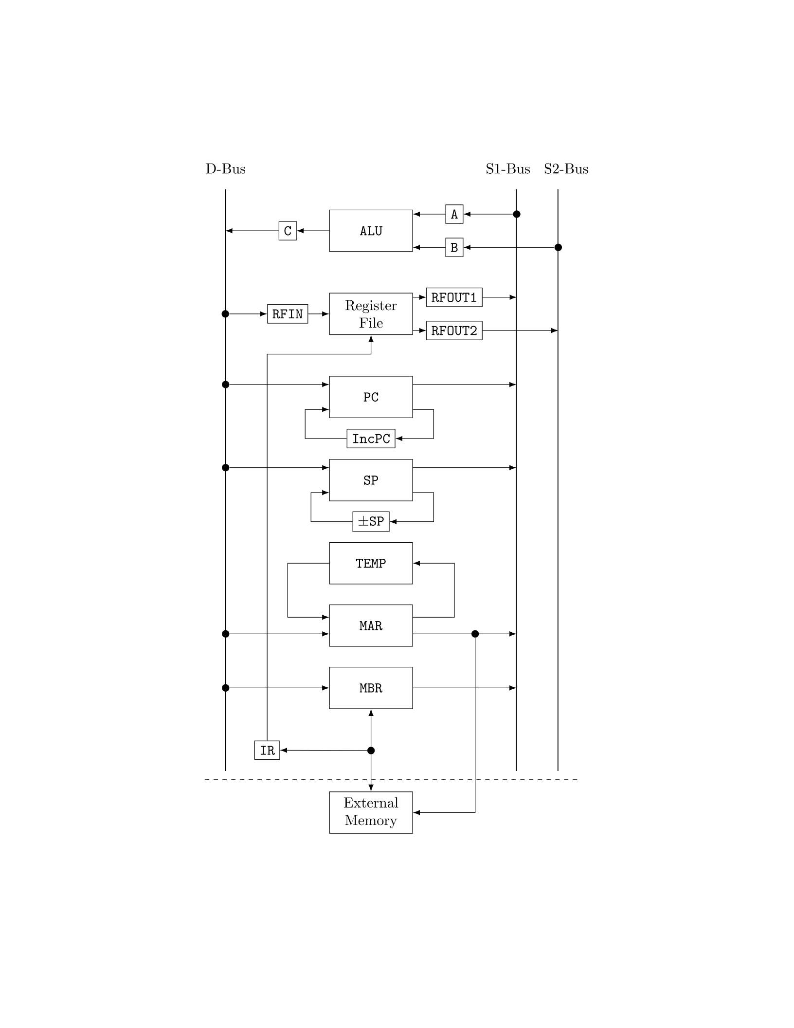
ALU
A
B
C
Register
File
RFOUT1
RFOUT2
RFIN
PC
IncPC
SP
±SP
TEMP
MAR
MBR
External
Memory
IR
D-Bus S1-Bus S2-Bus
Figure 1: A simplified CPU
In this assignment, extra instructions are added. They are the PUSH, POP, CALL and RET instruction. In order to implement
these instructions, the CPU is modified as follows:
1. A new register (SP, the stack pointer) is included. SP provides output to S1-bus, and receives input from D-bus. Also, the
Page 1 of 6
Page 1 of 6
SP has special hardware to increase and decrease its value by 4 (similar to PC). This is provided by the special function
do incSP(), and do decSP(), which is in turn controlled by the flag incSP and decSP.
2. A new register (TEMP) is included, which is directly connected to the MAR only, via a dedicated data path. Again you can move
data between MAR and TEMP and special function do MAR to TEMP() and do TEMP to MAR() are provided, which are
controlled by the MAR to TEMP and TEMP to MAR flag.
3. A new flag push pop is included, which will move the SP to MAR. Otherwise, the CPU remains the same.
New instructions provided include:
PUSH Rn : SP ← SP-4; mem[SP] ← Rn
00001010 n 00000000 00000000
POP Rn : Rn ← mem[SP]; SP ← SP+4
00001011 00000000 00000000 n
CALL proc :
00001100 00000000 11111111 00000000
RET :
00001101 00000000 00000000 00000000
Summary Opcode:
Instruction Opcode Instruction Opcode Instruction Opcode
ADD 00000000 MOV 00000101 PUSH 00001010
SUB 00000001 LD 00000110 POP 00001011
NOT 00000010 ST 00000111 CALL 00001100
AND 00000011 Bcc 00001000 RET 00001101
OR 00000100 HLT 00001001
The Program
The revised simulator program is given in sim2.py. Study the simulator code carefully.
1. Hand assemble the following assembly code and put it in a program file. Run the simulator on this program. Explain what the
function SQ does?
SUB R4,R4,R4 0000H: 01040404
LD P1,R1 0004H: 0600ff01 00000078
MOV R1,R2 000CH: 05010002
LD P2,R3 0010H: 0600ff03 0000007c
L: MOV R1,R10 0018H: 0501000a
CALL SQ 001CH: 0c00ff00 00000044
ADD R4,R11,R4 0024H: 00040b04
ADD R1,R2,R1 0028H: 00010201
SUB R3,R1,R5 002CH: 01030105
BNZ L 0030H: 0802ff00 00000018
ST R4,P 0038H: 0704ff00 00000080
HLT 0040H: 09000000
/
*
Procedure to calculate <????????>, input is R10, output is R11
*
/
/
*
The proc uses R12 and R13, need to save them on entry
*
/
/
*
and restore them on exit
*
/
SQ: PUSH R12 0044H: ....
PUSH R13 0048H: ....
LD P1,R13 004CH: ....
SUB R13,R13,R13 0054H:
Page 2 of 6
Page 2 of 6

MOV R10,R12 0058H:
L2: ADD R11,R10,R11 005CH:
SUB R12,R13,R12 0060H:
BNZ L2 0064H:
POP R13 006CH:
POP R12 0070H:
RET 0074H:
P1 .WORD 1 0078H: 00000001
P2 .WORD A 007CH: 0000000a
P .WORD 0080H: 00000000
Solution: SQ reads register R10 as input, and calculate the square of the value of R10, and set the result at register R11 as
output.
The complete assembled code is as follows:
01040404
0600ff01
00000078
05010002
0600ff03
0000007c
0501000a
0c00ff00
00000044
00040b04
00010201
01030105
0802ff00
00000018
0704ff00
00000080
09000000
0a0c0000 ; SQ: PUSH R12
0a0d0000 ; PUSH R13
0600ff0d ; ...
00000078 ;
010b0b0b ;
050a000c ;
000b0a0b ;
010c0d0c ;
0802ff00 ;
0000005c ;
0b00000d ; ...
0b00000c ; POP R12
0d000000 ; RET
00000001
0000000a
00000000
2. Run the simulator in debug mode. Write down the data transfer/transformation sequences involved in the execution of the
instructions CALL and RET. You may skip intermediate step provided by the simulator, for example the in struction fetchs step
should look like:
MAR <- PC
IR <- mem[MAR]
Page 3 of 6
Page 3 of 6

or in English, move the value of PC to MAR. Then read memory and the result (mem[MAR]) is moved to IR, i.e. just write down
the source and destination of the data movement, without the paths etc.
Solution: The comments in the code are optional and are not required for the submission.
For CALL instruction:
MAR <- PC ; instruction fetch
IR <- mem[MAR]
MAR <- PC ; address of next word
MBR <- mem[MAR] ; reads address of called instruction
MAR <- MBR
PC <- PC + 4 ; point to the instruction after return
TEMP <- MAR ; put called instruction address in TEMP
SP <- SP { 4 ; decrement stack ptr for pushing
MAR <- SP ; get address for pushing to top of stack
MBR <- PC ; put return target in MBR
mem[SP] <- MBR ; push return target to stack
MAR <- TEMP ; retrieve called instruction address
PC <- MAR ; point PC to called instruction
For RET instruction:
MAR <- PC ; instruction fetch
IR <- mem[MAR]
MAR <- SP ; get address of top of stack
SP <- SP + 4 ; pop (increment ptr)
MBR <- mem[MAR] ; pop top of stack to MBR (return address)
PC <- MBR ; point PC to where the routine was suspended
3. Modify the program so that it will calculate the value of 1 − 2 + 3 − 4 + · · · − 8 + 9. That is,
sum = 0;
for i=1 to 9 do sum += sq(i)
Where sq(i) return i when i is odd, otherwise return -i. Note that the original program is already a loop from 1 to 9. Just
replace the function SQ by
if (R10 is odd) R11 = R10;
else R11 = 0 - R10;
Since we don’t have a NEG instruction, to find x, we use 0 − x. To check if a number x is odd, just check if the rightmost bit is 1.
We can find x AND 00000000...0001. (i.e. 1) After AND operation, all bits ANDed with 0 will be 0. If the rightmost bit is
0, then the result is 0. Otherwise the result is non-zero. Note that the address of P1, P2 and P may got changed when the length
of the function SQ is changed. You may need to change the address of them in the program, e.g. in line 2
LD P1,R1
you may need to find the new address of P1, and also in line 4...
Page 4 of 6
Page 4 of 6

Solution: The modified assembly code is as follows:
SUB R4,R4,R4
LD P1,R1
MOV R1,R2
LD P2,R3
L: MOV R1,R10
CALL SQ
ADD R4,R11,R4
ADD R1,R2,R1
SUB R3,R1,R5
BNZ L
ST R4,P
HLT
SQ: PUSH R12
PUSH R13
LD P1,R13 ; set R13 = 1 for odd/even check
SUB R12,R12,R12 ; set R12 = 0 for negation
AND R10,R13,R11 ; store result at R11
BNZ OD ; if not 0 -> odd -> jump to OD
SUB R12,R10,R11 ; input is even, negate it and put in R11
BR RT ; jump to RT to prepare for return
OD: MOV R10,R11 ; if odd, copy R10 to R11 diretly
RT: POP R13
POP R12
RET
P1: .WORD 1
P2: .WORD A
P: .WORD
It’s assembled hexadecimal code is as follows:
01040404
0600ff01
00000080
05010002
0600ff03
00000084
0501000a
0c00ff00
00000044
00040b04
00010201
01030105
0802ff00
00000018
0704ff00
00000088
09000000
0a0c0000
0a0d0000
0600ff0d
00000080
010c0c0c
030a0d0b
0802ff00
00000070
Page 5 of 6
Page 5 of 6

010c0a0b
0800ff00
00000074
050a000b
0b00000d
0b00000c
0d000000
00000001
0000000a
00000000
Page 6 of 6
Page 6 of 6
See also
-
COMP2120-Assignment1
Assignment 1 of COMP2120 (24/25 Spring) with solutions.
-
COMP2120-Assignment2
Assignment 2 of COMP2120 (24/25 Spring) with solutions.
-
COMP2120-Assignment3
Assignment 3 of COMP2120 (24/25 Spring) with solutions.
-
COMP2120-Assignment5
Assignment 5 of COMP2120 (24/25 Spring) with solutions.
-
COMP2120-Cheatsheet
An A4 double-sided cheatsheet for the COMP2120 final exam.
-
COMP2120-Notes
Revision notes for COMP2120.