235 Signal["move_via_S1"] = 1 # Enable data movement through S1-bus
236 Signal["move_via_S2"] = 1 # Enable data movement through S2-bus
237 Signal["move_via_D"] = 1 # Enable data movement through D-bus
238 Signal["read_memory"] = 0 # Disable memory read (not a load instruction)
239 Signal["write_memory"] = 0 # Disable memory write (not a store instruction)
240 Signal["dohalt"] = 0 # Do not halt the processor
347 def set_ST():
348 # Fill in the code for ST instruction here
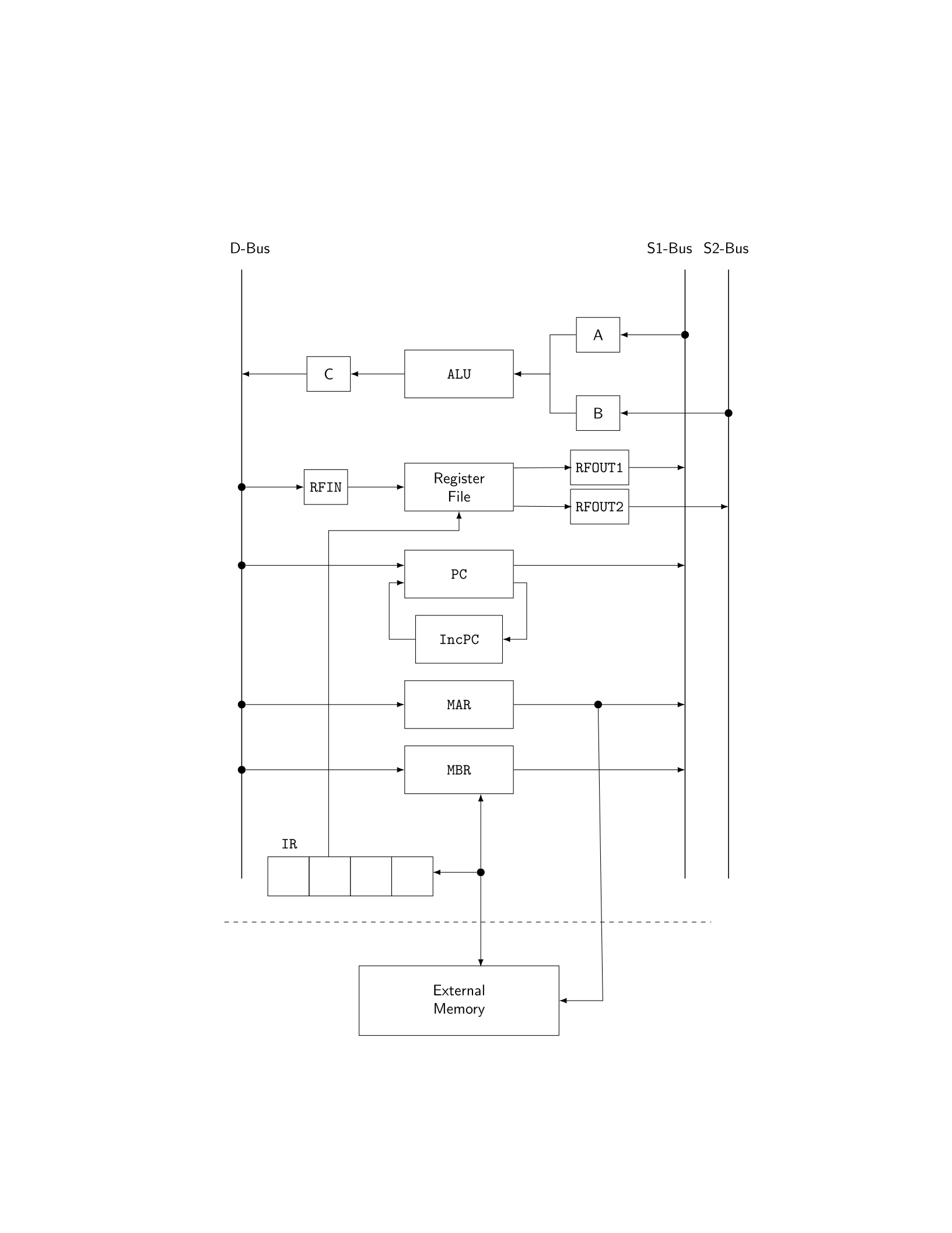
349 Signal["calc_addr"] = 1 # Enable address calculation (needed for 0xFF mode)
350 Signal["branch"] = 0 # This is not a branch instruction
351 Signal["read_RF_port_1"] = 1 # Enable read from RF1 (source operand - register)
352 Signal["read_RF_port_2"] = 0 # Disable read from RF2 (not needed for store)
353 Signal["write_RF"] = 0 # Disable writing to register file (storing to memory)
354 Signal["src_of_S1"] = "RFOUT1" # Connect S1-bus source to register file output port 1
355 Signal["dst_of_S1"] = "A" # Route S1-bus destination to ALU input A
356 Signal["src_of_S2"] = "" # S2-bus source not needed (no second operand)
357 Signal["dst_of_S2"] = "" # S2-bus destination not needed (no second operand)
358 Signal["src_of_D"] = "C" # Connect D-bus source to ALU output C
359 Signal["dst_of_D"] = "MBR" # Route D-bus destination to Memory Buffer Register
360 Signal["doalu"] = 1 # Enable ALU operation
361 Signal["ALU_func"] = "OP_COPY" # Set ALU function to copy operation (pass data through)
362 Signal["move_via_S1"] = 1 # Enable data movement through S1-bus
363 Signal["move_via_S2"] = 0 # Disable data movement through S2-bus (not used)
364 Signal["move_via_D"] = 1 # Enable data movement through D-bus
365 Signal["read_memory"] = 0 # Disable memory read (this is a store, not load)
366 Signal["write_memory"] = 1 # Enable memory write (store data to memory)
367 Signal["dohalt"] = 0 # Do not halt the processor
Running the simulator program:
[python3] sim.py [-d] prog
If -d option is specified, the program will print out debug information. The simulator obtains input program from the file prog.
Test you simulator with the following simple program:
LD P0,R4 0000: 0600ff04 0000003c
LD P1,R1 0008: 0600ff01 00000040
MOV R1,R2 0010: 05010002
LD P2,R3 0014: 0600ff03 00000044
L: ADD R4,R1,R4 001C: 00040104
ADD R1,R2,R1 0020: 00010201
SUB R3,R1,R5 0024: 01010305
BNZ L 0028: 0802ff00 0000001c
ST R4,P 0030: 0704ff00 00000048
HLT 0038: 09000000
P0: .WORD 0 003C: 00000000
P1: .WORD 1 0040: 00000001
P2: .WORD A 0044: 0000000a
P: .WORD 0048: 00000000
What does this program do?
Solution: The program computes the sum of integers from 1 to 9.
Explanation: After the first four lines, the registers are initialized as follows:
• R4 = 0 (loaded from memory address P0 - 0x3C)
Page 4 of 6